-40%
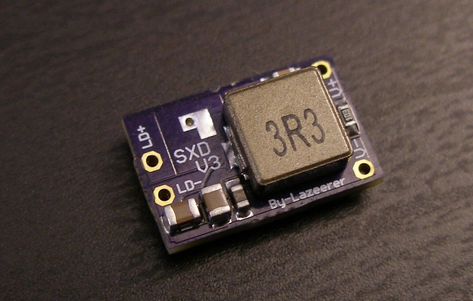
4.5A SXD Super X-Drive Laser Driver NDB7A75 - NUBM44 - NUMB05 - NUBM06 - NUBM08
$ 15.83
- Description
- Size Guide
Description
Listing is for a single SXD Super X-Drive Bucking Laser Driver preset to 4.5A. The Sueper X-Drive is an extremely efficient buck style regulator with many built in safety features to protect and give long life to your laser diodes. Driver has soft start, overshoot protection and very low noise. The driver can operate without an external heat sink with the current up to 1.5A , but it requires a heat sink for currents above 1.5A if you want continuous operation.It works with 2 or 3 cells Li-Ion or 6.5V-12V DC PSU.
Highly suggest not using 2S or 3S Lipo packs. Being designed for extremely high current instant
demand
loads like electric motors commonly used with RC builds. Many examples of them overwhelming the inductance
suppression
on many types of IC's with both
voltage
transients
and reverse bias spikes on disconnect. Stick with Li-ions. Two Li-ions are the suggested setup if powering via batteries.
Don't power the driver without a load connected like connecting the driver directly to a DMM. If testing the driver remove laser diode and connect to a simulated load in series with a DMM to read the current setting or use what is commonly
referred
to as a "test load" which you can build a simple unit or there are some nice premade units with large sinked voltage drop diodes with selectable numbers of diodes. When connected to a laser diode a secure soldered
connection
between the laser driver and
diode
without anything else in series on the output of the driver. A quick connect can be used on the input side of the driver but a secure permanent connection should be used between the driver and diode.
Here are a some pictures of the dimensions:
SXD Super X-Drive PWM/TTL control. These instructions are only if you plan to use TTL to control the driver. If you don't plan on using TTL the driver will work as is no need to modify anything.:) PWN/TTL Modulation Frequency: Up to 1kHz Modulation Voltage 0-5V Full range: 1.6V ON "Max 12V" & 0.6V - 0V OFF
Solder the modulation Wire to the Yellow Arrow after removing the 10K.^^^^ Like SO:
Enable Pin is High "ON" Minimum 1.6V with an Ultimate MAX of 12V input Enable Pin is Low "OFF" 0.6V or lower 12V MAX the enable pin can take.
Remove the Ramp Up Capacitor.


